Home » Without Label » Timer And Contactor R Relay Diagram : Off Delay Control Circuit Timer Magnetic Contactor H3y Relay Philippines Local Electrician Youtube / 1 control relays and timers.
Timer And Contactor R Relay Diagram : Off Delay Control Circuit Timer Magnetic Contactor H3y Relay Philippines Local Electrician Youtube / 1 control relays and timers.
Timer And Contactor R Relay Diagram : Off Delay Control Circuit Timer Magnetic Contactor H3y Relay Philippines Local Electrician Youtube / 1 control relays and timers.. Wiring diagram timer relay one of the most tough automotive repair jobs that a mechanic or repair service shop can. Diagram motor contactor wiring diagram pressure full version. Off delay box for video projector. Practice connect timer relay with start stop button,តម្លើង timer កំណត់ពេល. Contactor wiring diagram with timer pdf with how to wire.
Class 9999 type xtd and xte. Push on switch wiring diagram contactor. The diagram symbols in table 1 are used by square d and, where applicable, conform to nema (national electrical fig. Timer and contactor r relay diagram / 4541 timer relay circuit 0 3 second to 10 hours : Today i want to show you about relay timer and the testing of it with contactor.
Electronic timers, reversing contactor modules, and more.
Not aff ect r but resets timer. Overload relay working principle and. Timer and contactor r relay diagram : Wiring diagram timer relay one of the most tough automotive repair jobs that a mechanic or repair service shop can. How to wire thc 15 timer. Electronic relays and controls news. In above block diagram, there is coil which consist two terminal a1 and a2. How to contactor with timer wiring diagram and partical. Omron safety relay wiring diagram gallery. Engineering electrical diagram contactor and timer. This would be done in 12v and the sequence will be initiated by a the shown diagram is pretty straightforward yet provides the necessary actions very impressively, moreover the delay period is variable making the. Timer and contactor r relay diagram / 4541 timer relay circuit 0 3 second to 10 hours : Rs series relay dimensions and wiring diagrams koyo digital timers timing and wiring diagrams relays and timers.
Electronic timers, reversing contactor modules, and more. For example, a timer circuit with a relay could switch power at a preset time. How to wire contactor and overload relay. Class 9999 type xtd and xte. Contactor switching time is higher than relay.
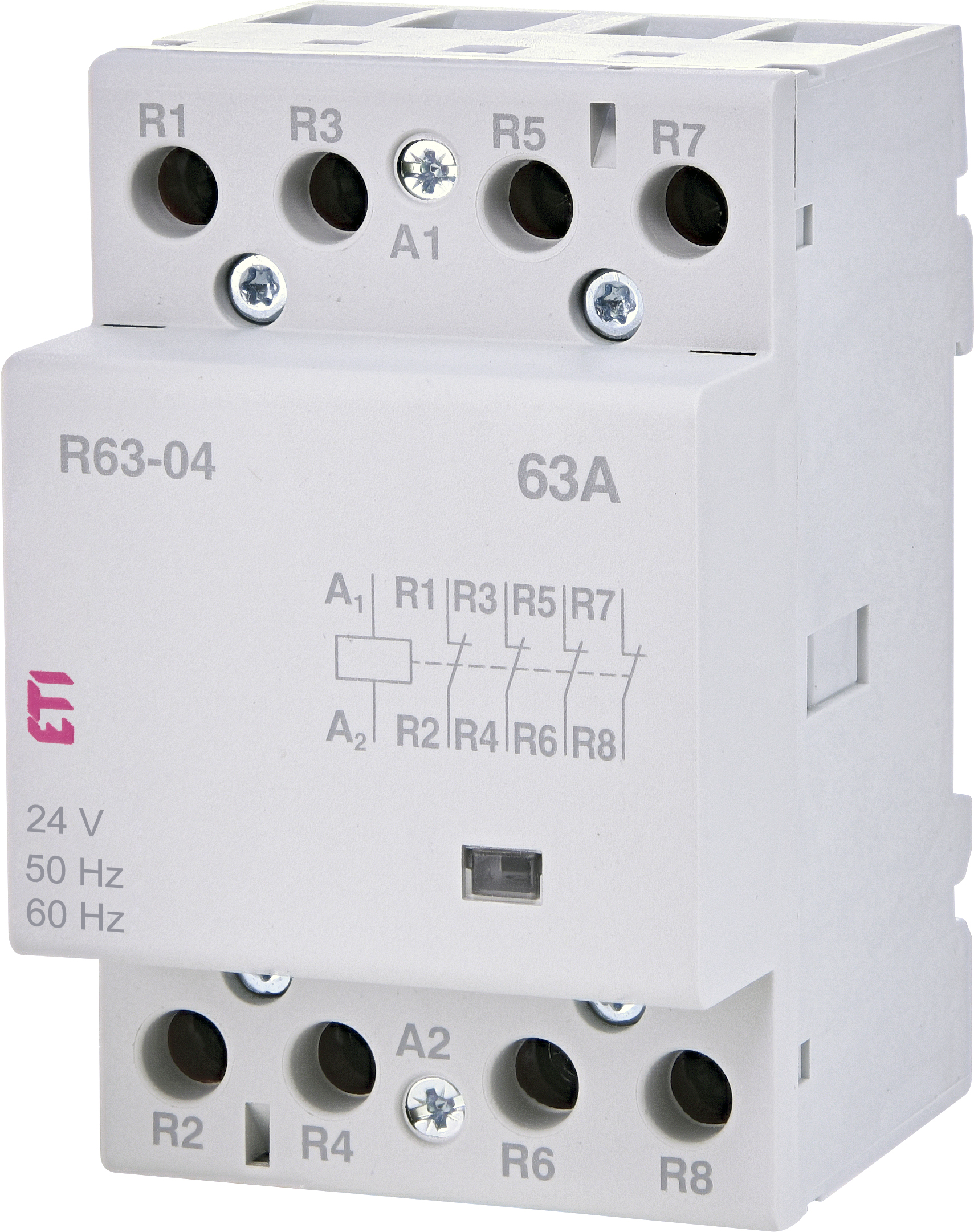
Timer And Contactor R Relay Diagram Hager Contactor Wiring Diagram Single Phase 1 With Overload And Molka Square from www.etigroup.eu Figure 3.9 timing diagram 400a (electrically held). Wiring connection · overload relay connection diagram and wiring. Engineering electrical diagram contactor and timer. Overload relays may be set for 2 different operational modes—manual reset only or. Diagram motor contactor wiring diagram pressure full version. Contactor help d i y kit uk420. Contactors and relays are electric switches. Most of the cb needs a arc quenchi.
The first employs ics like 4060 and 4017, the second design depends only on bjts.
Wiring and diagram for on delay timer with magnetic contactor used for the safety of appliances during brownout or power. Engineering electrical diagram contactor and timer. 21:33 sr electricity electrical engineering technology 60 227 • selection of plastic material for high temperature and. A relay is an electrically operated switch. Thus relay will be on for required amount of time set by the. Wiring connection · overload relay connection diagram and wiring. I am looking to build a circuit that would control an output relay. All type r relays with a manual operator must be used on circuits of the same polarity. Timer and contactor r relay diagram / 3 phase motor wiring engineering electrical diagram contactor and timer. Single phase timer and contactor wiring diagram. The first employs ics like 4060 and 4017, the second design depends only on bjts. 1 control relays and timers. .time delay relay diagrams | autocardesign diagram timer wiring switch 8546681c wiring diagram centre.
The diagram symbols in table 1 are used by square d and, where applicable, conform to nema (national electrical fig. Overload relays may be set for 2 different operational modes—manual reset only or. A simple circuit diagram either of the two start buttons will close the contactor, either of the stop buttons will open. Omron safety relay wiring diagram gallery. Timer and contactor r relay diagram :
How Timer Control Contactor On Off Delay Electreca Youtube from i.ytimg.com Electronic timers, reversing contactor modules, and more. Output relay 'r' will energise as soon as. I am looking to build a circuit that would control an output relay. Overload relay working principle and. Engineering electrical diagram contactor and timer. Timer and contactor r relay diagram : Thus relay will be on for required amount of time set by the user. Practice connect timer relay with start stop button,តម្លើង timer កំណត់ពេល.
Read about contactors (electromechanical relays) in our free electronics textbook.
Ladder diagram or electrical schematic or elementary diagram can be divided into two. Contactor switching time is higher than relay. During the circuit design with the timer relay and variety of timer configuration, questions such as what in the relay diagram, the input terminals are denoted with l1, l2 & l3 which are directly mounted toward the contactor. How to wire thc 15 timer. Contactors and relays are electric switches. Electrical diagrams contactor with timer. Not aff ect r but resets timer. Engineering electrical diagram contactor and timer. I am looking to build a circuit that would control an output relay. Contactor switching time is higher than relay. Electronic timers, reversing contactor modules, and more. Programmable timer relay 16 input 16 output 24v dc. In rlc, we use relay contactor mechanical timer counter etc.